Series 100/200 l 0.8 to 3.0 Amperes
100/200 Series
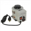
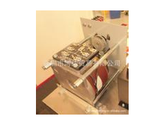
These manually operated panel mounted units are available in
single and three phase models from 0.8 to 3.0 amperes. The
171, 201, 221-B and 291 units operate from 120 volt input,
while the 252 unit operates from a 240 volt input. STACO’s coil
tapping arrangement permits an output voltage from 0 to line
voltage in either the clockwise or counterclockwise direction
and from 0 to 10% above line voltage in the clockwise direction.
Two and three ganged, manually operated units are available
for increased single phase voltage ratings and for three
phase applications.
INPUT OUTPUT TERMINAL CONNECTIONS
CONSTANT CONSTANT SHAFT
(For increasing Voltage)
PART NO. WIRING VOLTS HERTZ VOLTS CURRENT IMPEDANCE ROTATION
As Viewed from Base End
SCHE- NET
LOAD LOAD FOR MATIC WT.
MAX MAX MAX MAX VOLTAGE Input Jumper• Output (Pg 8 & 9) LBS.
AMPS KVA AMPS KVA INCREASE
Single 120 50/60 0-120 1.75 0.21 2.2 0.26 CW 1-2 — 1-3
171 Phase CCW 1-2 — 2-3 1 2
60 0-132 1.75 0.23 – – CW 1-4 — 1-3
Single 50/60 0-240 1.75 0.42 2.2 0.53 CW 2-2 1-1 3-3
Phase 240 CCW 1-1 2-2 3-3 1&4 4 1/4
Series 60 0-264 1.75 0.46 – – CW 4-4 1-1 3-3
171-2 Three 50/60 0-120 1.75 0.36 2.2 0.46 CW 2-1-2 1-1 3-1-3
Phase 120++ — — CCW 1-2-1 2-2 3-2-3 1 & 5 4 1/4
Open
Delta π 60 0-132 1.75 0.40 — — CW 4-1-4 1-1 3-1-3
Three CW 2-2-2 1-1-1 3-3-3
171-3 Phase 240++ 60 0-240 1.75 0.73 2.2 0.92
CCW 1-1-1 2-2-2 3-3-3
1 & 6 6 1/2
Wye π
Single 50/60 0-120 2.0 0.24 2.5 0.30 CW 1-2 — 1-3
201 Phase 120 CCW 1-2 — 2-3 1 2
60 0-132 2.0 0.26 — — CW 1-4 — 1-3
Single 50/60 0-240 2.0 0.48 2.5 0.60 CW 2-2 1-1 3-3
Phase 240 CCW 1-1 2-2 3-3 1 & 4 4 1/4
Series 60 0-264 2.0 0.53 — — CW 4-4 1-1 3-3
201-2 Three 50/60 0-120 2.0 0.42 2.5 0.52 CW 2-1-2 1-1 3-1-3
Phase 120++ CCW 1-2-1 2-2 3-2-3 1 & 5 4 1/4 Open
Delta π 60 0-132 2.0 0.46 — — CW 4-1-4 1-1 3-1-3
Three CW 2-2-2 1-1-1 3-3-3 201-3 Phase 240++ 60 0-240 2.0 0.83 2.5 1.04
CCW 1-1-1 2-2-2 3-3-3
1 & 6 6 1/2
Wye π
Single 50/60 0-120 2.5 0.30 3.2 0.38 CW 1-2 — 1-3
221-B Phase 120 CCW 1-2 — 2-3 1 2 1/2
60 0-132 2.5 0.33 — — CW 1-4 — 1-3
Single 50/60 0-240 2.5 0.60 3.2 0.77 CW 2-2 1-1 3-3
Phase 240 CCW 1-1 2-2 3-3 1 & 4 5 1/2
Series 60 0-264 2.5 0.66 — — CW 4-4 1-1 3-3
221-B-2 Three CW 2-1-2 1-1 3-1-3
Phase 120++
50/60 0-120 2.5 0.52 3.2 0.67 CCW 1-2-1 2-2 3-2-3 1 & 5 5 1/2
Open
Delta π 60 0-132 2.5 0.57 — — CW 4-1-4 1-1 3-1-3
Three CW 2-2-2 1-1-1 3-3-3
221-B-3 Phase 240++ 60 0-240 2.5 1.04 3.2 1.33
CCW 1-1-1 2-2-2 3-3-3
1 & 6 8 1/4
Wye π
3PN221B
Single 120 60 0-132 2.50 0.33 — — CW LINE CORD & RECEPTACLE 3 3 Phase
Single 50/60 0-240 0.8 0.19 1.0 0.24 CW 1-2 — 1-3
252 Phase 240 CCW 1-2 — 2-3 1 2 1/2
60 0-264 0.8 0.21 — — CW 1-4 — 1-3
Single CW 2-2 1-1 3-3
Phase 480 50/60 0-480 0.8 0.38 1.0 0.48
CCW 1-1 2-2 3-3 1 & 4 5 1/2
Series 60 0-528 0.8 0.42 — — CW 4-4 1-1 3-3
252-2 Three 50/60 0-240 0.8 0.33 1.0 0.42 CW 2-1-2 1-1 3-1-3
Phase 240++ CCW 1-2-1 2-2 3-2-3
Open 60 0-264 0.8 0.37 — — CW 4-1-4 1-1 3-1-3
1 & 5 5 1/2
Delta π
Three 50/60 0-480 0.8 0.67 1.0 0.83 CW 2-2-2 1-1-1 3-3-3
252-3 Phase 480++ CCW 1-1-1 2-2-2 3-3-3 1 & 6 8 1/4
Wye π 60 0-528 0.8 0.73 — — CW 4-4-4 1-1-1 3-3-3
221-B
Single Unit
Two and Three Gang Units
View from
Base End
201-3
100/200 Series
INPUT OUTPUT TERMINAL CONNECTIONS
CONSTANT CONSTANT SHAFT
(For increasing Voltage)
PART NO. WIRING VOLTS HERTZ VOLTS CURRENT IMPEDANCE ROTATION
As Viewed from Base End
SCHE- NET
LOAD LOAD FOR MATIC WT.
MAX MAX MAX MAX VOLTAGE Input Jumper• Output (Pg 8 & 9) LBS.
AMPS KVA AMPS KVA INCREASE
Single 50/60 0-120 3.0 0.36 3.5 0.42 CW 1-2 — 1-3
291 Phase 120 CCW 1-2 — 2-3 1 2 1/2
60 0-132 3.0 0.40 — — CW 1-4 — 1-3
Single 50/60 0-240 3.0 0.72 3.5 0.84 CW 2-2 1-1 3-3
Phase 240 CCW 1-1 2-2 3-3 1 & 4 5 1/2
Series 60 0-264 3.0 0.79 — — CW 4-4 1-1 3-3
291-2 Three 50/60 0-120 3.0 0.62 3.5 0.73 CW 2-1-2 1-1 3-1-3
Phase 120++ CCW 1-2-1 2-2 3-2-3 Open 1 & 5 5 1/2
Delta π 60 0-132 3.0 0.69 — — CW 4-1-4 1-1 3-1-3
Three CW 2-2-2 1-1-1 3-3-3
291-3 Phase 240++ 60 0-240 3.0 1.25 3.5 1.45
CCW 1-1-1 2-2-2 3-3-3
1 & 6 8 1/4
Wye π
• Jumper provided in the standard common position and should be moved or removed as required.
++ Line to line voltage
π If ganged units are used in a system that ordinarily has a common neutral or ground between source and load, the neutral or ground must be connected to the common
terminals of the variable transformer assembly. If the system has no neutral, the load must be balanced or the transformers will be damaged.
120V 240V
TYPE B
171-2, 201-2 4.66” [118.3]
171-3, 201-3 7.38” [187.2]
221-B-2, 252-2 5.16” [131.0]
221-B-3, 252-3 8.12” [206.4]
291-2 5.59” [142.1]
291-3 8.81” [223.8]
TYPE A
171, 201 1.88” [47.6]
221-B, 252 2.12” [54.0]
291 2.31” [58.7]
源自:深圳市湾边贸易有限公司
网址:http://www.coastaltrading.com.cn (中文)
web :http://www.coastbuyer.com (English)
电话:0755-8621 6601
QQ 1191737095
备注:产品价格与描述不同,具体请来电咨询!


